
Continuations Specification
Introduction
Overview
An app execution may require arbitrarily many steps, but each proof covers a bounded number of steps. OpenVM thus splits execution into segments and produces one proof per segment. Continuation is the process of recursively aggregating segment proofs into (usually) a single proof by:
- Verifying child proofs from adjacent segments
- Verifying public value consistency between adjacent child proofs
- Outputting a proof attesting to 1 and 2
This forms an aggregation tree with multiple layers, where each layer aggregates child proofs from the layer below. There are six layer types:
| Layer | Description |
|---|---|
| app | Executes a program on the VM, then produces one Proof per segment and a Merkle proof of user public values' presence in the final memory state |
| leaf | Aggregates up to app segment Proofs into a single Proof |
| internal-for-leaf | Aggregates up to leaf Proofs into a single Proof |
| internal-recursive | Aggregates up to internal-for-leaf Proofs, or up to internal-recursive Proofs. Note is the same at all internal layers. |
| root | Wraps a single internal-recursive Proof and verifies user public values exist in final memory |
| static | Re-encodes root Proof into a fixed, constant-sized format for on-chain verification |
The first five types each correspond to a unique STARK-based circuit. The static layer is handled separately — it re-encodes a root Proof for on-chain verification. Because this encoding must be constant-sized, the root Proof size must also be fixed.
Circuit and Prover Definitions
A circuit is a set of AIRs that collectively constrain one or more trace matrices and expose a fixed set of public values. A subcircuit is a subset of a circuit's AIRs.
A prover is a struct that generates a proof for a specific circuit given appropriate inputs. We distinguish:
- Basic provers — generate a single aggregated
Prooffrom childProofs. Each basic prover corresponds to a specific aggregation subcircuit (see Layer Architecture for more information). - SDK provers — orchestrate basic provers to produce client-facing proof formats (
ContinuationVmProof,VmStarkProof,EvmProof) or their intermediate forms.
Client-Facing Proofs
There are three client-facing proof types:
| Type | Struct | Description |
|---|---|---|
| App proof | ContinuationVmProof | Non-aggregated segment Proofs plus the user public values Merkle proof |
| STARK proof | VmStarkProof | A single aggregated Proof plus the user public values Merkle proof |
| EVM proof | EvmProof | A single, constant-sized aggregated Proof formatted for verification by a fixed on-chain verifier |
Aggregation Pipelines
Each client-facing proof type requires a specific aggregation pipeline:
| Proof Type | Pipeline |
|---|---|
| App | app (no aggregation) |
| STARK | app → leaf → internal-for-leaf → internal-recursive (repeated at least until one Proof remains) |
| EVM | app → leaf → internal-for-leaf → internal-recursive (repeated at least until one Proof remains) → root → static |
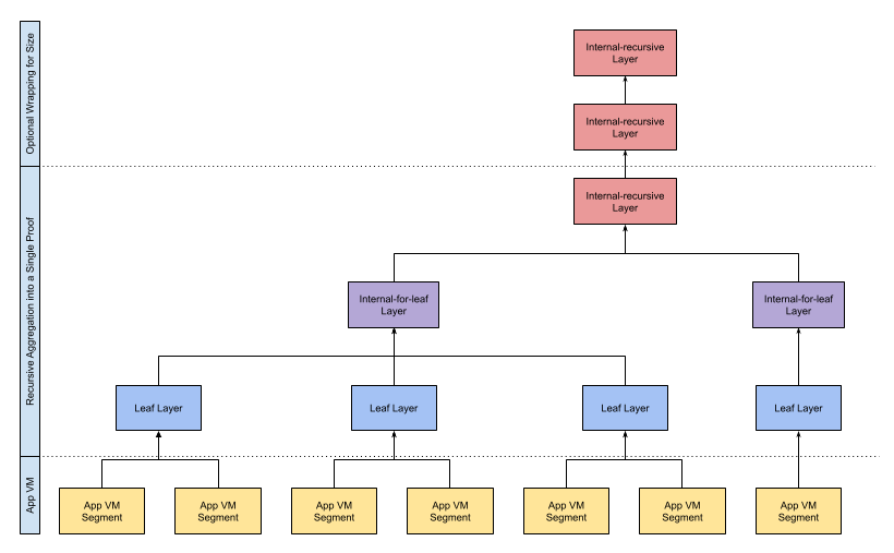
Diagram of a potential STARK proof aggregation tree with 2:1 max leaf aggregation and 3:1 max internal aggregation.
SDK Provers
For convenience the SDK provides several SDK provers, which orchestrate basic provers to produce client-facing proof formats. Most wrap disjoint aggregation pipeline sections; we informally denote these "component SDK provers".
| Component SDK Prover | Aggregation Pipeline Section | Input | Output |
|---|---|---|---|
AppProver | app | Executable and StdIn input | ContinuationVmProof (i.e. app proof) |
AggProver | leaf → internal-for-leaf → internal-recursive (repeated at least until one Proof remains) | ContinuationVmProof | VmStarkProof (i.e. STARK proof) |
RootProver | root | VmStarkProof | Proof (EVM input) |
Halo2Prover | static | Proof | EvmProof (EVM proof) |
StarkProver and EvmProver use these component SDK provers to encapsulate end-to-end STARK and EVM proving.
| E2E SDK Prover | Component Prover Pipeline | Input | Output |
|---|---|---|---|
StarkProver | AppProver → AggProver | Executable and StdIn input | VmStarkProof |
EvmProver | AppProver → AggProver → RootProver → Halo2Prover | Executable and StdIn input | EvmProof |
Layer Architecture
Every non-app STARK-based layer has a circuit composed of exactly two subcircuits:
- A verifier subcircuit — verifies child proofs individually
- An aggregation subcircuit — enforces public value consistency across child proofs and exposes public values for the next layer
Different layers may share the same verifier subcircuit or the same aggregation subcircuit, but each layer's circuit is a unique pairing.
| Layer | Verifier Subcircuit | Aggregation Subcircuit |
|---|---|---|
| app | (VM execution) | (none) |
| leaf | leaf | inner |
| internal-for-leaf | internal-for-leaf | inner |
| internal-recursive | internal-recursive | inner |
| root | internal-recursive | root |
Note that leaf, internal-for-leaf, and internal-recursive all share the inner aggregation subcircuit and therefore have the same public value layout. Root reuses the internal-recursive verifier subcircuit but pairs it with a different aggregation subcircuit.
Verifying Key Convergence
Each verifier subcircuit is parameterized by the child proof's verifying key (child_vk). Because the verifier subcircuit depends on child_vk, each layer initially has a different circuit:
- leaf circuit is derived from
app_vk - internal-for-leaf circuit is derived from
leaf_vk - internal-recursive circuit is derived from
internal_for_leaf_vk
However, the system is designed so that the circuit converges at the internal-recursive layer. This means:
- The verifier subcircuit derived from
internal_recursive_vkis identical to the internal-recursive verifier subcircuit itself - An internal-recursive
Proofcan be used as a child proof for another internal-recursive proof - For fixed internal system parameters, the internal-recursive circuit is the same for any
app_vk
This convergence property enables unbounded recursive aggregation.
Verifier Subcircuits
Shared Structure
All verifier subcircuits are semantically equivalent — each contains the same subset of AIRs that individually verify child proofs. However, the actual circuit constraints and parameters are derived from:
- The child proof's verifying key (
child_vk) - The maximum number of child
Proofs this subcircuit can verify ( for leaf, for internal, and 1 for root)
Because of the dependency on child_vk, different layers have different verifier subcircuits until convergence at internal-recursive.
Constraint DAG and Cached Traces
A verifier subcircuit must verify that a child proof satisfies the constraints defined by child_vk. These constraints are encoded as a constraint DAG, where each node represents a symbolic expression over trace values. This DAG includes interaction constraints.
To avoid recomputing the DAG in-circuit, verifier subcircuits use a cached trace: before proving, the DAG is serialized per-node into a cached trace, committed via SWIRL's stacked PCS, and the commitment is exposed as a public value. Each such commitment is paired with the child VK's field pre-hash (vk_pre_hash) to form a VK commit (VkCommit):
VkCommit {
cached_commit: [F; DIGEST_SIZE], // PCS commitment of the cached trace
vk_pre_hash: [F; DIGEST_SIZE], // field pre-hash of the child MultiStarkVerifyingKey
}The four VK commits are:
| Public Value | Commits to |
|---|---|
app_vk_commit | app_vk constraint DAG + VK pre-hash |
leaf_vk_commit | leaf_vk constraint DAG + VK pre-hash |
internal_for_leaf_vk_commit | internal_for_leaf_vk constraint DAG + VK pre-hash |
internal_recursive_vk_commit | internal_recursive_vk constraint DAG + VK pre-hash |
Each *_vk_commit is checked for consistency by the aggregation subcircuit and/or the final client-facing verifier. The cached_commit component is verified against the PCS commitment received from ProofShapeModule via the CachedCommitBus, while the vk_pre_hash component is verified via a separate PreHashBus.
| Subcircuit Layer | child_vk | Max child proofs |
|---|---|---|
| leaf | app_vk | |
| internal-for-leaf | leaf_vk | |
| internal-recursive | internal_for_leaf_vk |
As described in Verifying Key Convergence, the verifier subcircuit derived from internal_recursive_vk is identical to internal-recursive, enabling unbounded recursion. The internal-recursive verifier subcircuit can thus verify its own Proofs.
Aggregation Subcircuits
There are 2 aggregation subcircuit types: inner and root. Each type has an associated basic prover.
App Public Values and Shared Constraints
App public values are the public values exposed by the app layer. They are propagated through all aggregation layers.
initial_pc: F— starting PC value of the program/segmentfinal_pc: F— final PC value of the program/segmentexit_code: F— exit code of the program/segmentis_terminate: F— boolean flag indicating whether this segment terminated the programinitial_root: Digest— Merkle root of the initial memory statefinal_root: Digest— Merkle root of the final memory state
All aggregation subcircuits enforce segment adjacency constraints on the app public values. Given several adjacent segments, the aggregation subcircuit constrains that:
- The
final_pcandfinal_rootof each non-terminal segment equal theinitial_pcandinitial_rootof the segment immediately following it - Non-terminal segments have
is_terminate == 0andexit_code == DEFAULT_SUSPEND_EXIT_CODE - The terminal segment has
is_terminate == 1andexit_code == ExitCode::Success
The aggregation subcircuit also exposes public values necessary for either further recursive aggregation or final proof verification.
Inner Aggregation Subcircuit
The inner subcircuit takes up to child Proofs and does not constrain the user public values' presence in memory. Its output Proof is meant to either be recursively aggregated or used as the Proof component in a VmStarkProof.
Public Values
Public values are processed by VmPvsAir and VerifierPvsAir. The inner subcircuit re-exposes the app public values (excluding user_public_values) and adds the following verifier-specific public values, which are common over all inner layers:
-
Program Commit
program_commit: Digest— cached trace commit of the app circuit'sProgramAir
-
Aggregation Public Values
internal_flag: F— ternary flag indicating which verifier subcircuit this proof is for:0for leaf1for internal-for-leaf2for internal-recursive
app_vk_commit: VkCommit— VK commit (cached trace commit + VK pre-hash) for the leaf verifier subcircuit, derived fromapp_vkleaf_vk_commit: VkCommit— VK commit for the internal-for-leaf verifier subcircuit, derived fromleaf_vkinternal_for_leaf_vk_commit: VkCommit— VK commit for the first (index 0) internal-recursive layer verifier subcircuit, derived frominternal_for_leaf_vk
-
Internal Recursion-Related Public Values
recursion_depth: F— depth of the internal-recursive layer this proof is for:0for non-internal-recursive layers1for the first (index 0) internal-recursive layer2for the second (index 1) internal-recursive layer, and so on
internal_recursive_vk_commit: VkCommit— VK commit for each subsequent (index > 0) internal-recursive layer verifier subcircuit, derived frominternal_recursive_vk
The program_commit should be set at every layer, but the flags and *_vk_commits should be set according to which layer we are currently proving for. Unset *_vk_commits are filled with 0s.
| Layer | internal_flag | recursion_depth | app | leaf | internal_for_leaf | internal_recursive |
|---|---|---|---|---|---|---|
| leaf | 0 | 0 | set | unset | unset | unset |
| internal-for-leaf | 1 | 0 | set | set | unset | unset |
| internal-recursive (layer 0) | 2 | 1 | set | set | set | unset |
| internal-recursive (layer 1+) | 2 | 2+ | set | set | set | set |
Constraints
VerifierPvsAir constrains that:
- App segment proofs do not have inner subcircuit-specific public values
- Non-app child proofs within a layer have the same verifier-specific public values
- Child proof verifier-specific public values are set according to the table above
- Output proof verifier-specific public values match the child proofs':
- Flags are incremented properly
- The next unset
*_vk_commitis set (if any remain unset) - Previously defined
*_vk_commits match between child and output
Root Aggregation Subcircuit
The root subcircuit takes a single internal-recursive child Proof and does constrain the user public values' presence in memory. Its output Proof is meant to be the static layer input.
Public Values
The root subcircuit exposes a new set of public values for the static verifier. Segment adjacency public values are no longer needed since adjacency has already been enforced.
user_public_values: Vec<F>— user-defined public values stored in the public values address space during app executionapp_exe_commit: Digest— hashed combination of:- The app-level
ProgramAircached trace commit - The Merkle root of the starting app memory state (
initial_root) - The initial app program counter (
initial_pc)
- The app-level
app_vm_commit: Digest— commitment to the app VM verifier key, computed by hashing the 6 components of the child proof's app, leaf, and internal-for-leaf VK commits (cached_commitandvk_pre_hashfor each) viahash_slice
Constraints
The root subcircuit constrains the child proof's public values:
is_terminate == 1andexit_code == ExitCode::Success(successful app termination)internal_flag == 2andrecursion_depthis in[1, MAX_RECURSION_DEPTH](child is internal-recursive)- The verifier subcircuit's
SymbolicExpressionAircached commit andinternal_recursive_vk_commitare verified depending onrecursion_depth:recursion_depth == 1: cached commit is verified againstinternal_for_leaf_vk_commit.cached_commit, andinternal_recursive_vk_commitmust be unset (all zeros)recursion_depth > 1: cached commit is verified againstinternal_recursive_vk_commit.cached_commit, andinternal_recursive_vk_commit(bothcached_commitandvk_pre_hash) matches a pre-generated constant
The root subcircuit also constrains its own public values:
user_public_valueswere in the final memory state's public values address space, constrained by:- Computing the Merkle root of
user_public_values, denoteduser_pvs_commit - Constraining that a Merkle proof (where the path to the root depends on the
MemoryDimensions) exists betweenuser_pvs_commitandfinal_root
- Computing the Merkle root of
app_exe_commitis computed as specified aboveapp_vm_commitis computed from the child proof'sapp_vk_commit,leaf_vk_commit, andinternal_for_leaf_vk_commit(using all 6cached_commitandvk_pre_hashcomponents) as specified above
Deferral Integration
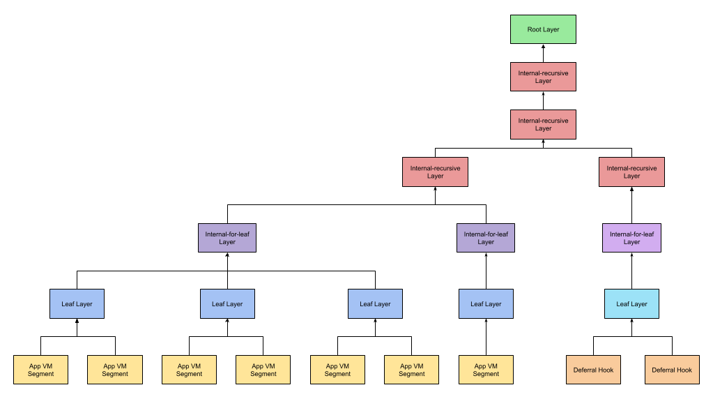
When the VM uses the deferral framework, deferral circuit proofs must be incorporated into the main aggregation tree. This section describes how deferral hook proofs join the continuation pipeline at the internal-recursive level.
Deferral Aggregation Overview
Each deferral circuit C_i produces its own proofs, which are aggregated through a separate per-circuit aggregation tree (leaf → internal-for-leaf → internal-recursive) using a deferral-specific inner aggregation subcircuit. This subcircuit builds Merkle trees of the input and output commits and propagates deferral VK commits.
The final internal-recursive proof for each C_i is then passed to a deferral hook layer, which:
- Verifies the child proof
- Converts the input and output commit Merkle roots into onion hashes (the hash-onion accumulators used by the VM)
- Exposes
DeferralPvscontaininginitial_acc_hashandfinal_acc_hash(the initial and final deferral accumulator values as memory subtree Merkle leaves),depth(the Merkle subtree depth), andnode_idx = def_idx - Computes and exposes a
def_hook_commitfrom the deferral circuit's VK commits
Combined VM-Deferral Tree
Deferral hook proofs are incorporated into the main aggregation tree at the internal-recursive level. The inner aggregation subcircuit supports a deferral_flag that indicates the type of child proofs:
deferral_flag | Child proof type |
|---|---|
0 | VM-only — child has VM public values (VmPvs) but no deferral public values |
1 | Deferral-only — child has deferral public values (DeferralPvs) but no VM public values |
2 | Combined — child has both VM and deferral public values |
At the leaf and early internal layers, VM segment proofs (deferral_flag=0) and deferral hook proofs (deferral_flag=1) are aggregated separately. When proofs of both types are combined in the same internal-recursive layer, the output proof has deferral_flag=2.
DeferralPvsAir processes and propagates the following DeferralPvs through the tree:
initial_acc_hash: Digest— Merkle root of all initial deferral accumulators aggregated so farfinal_acc_hash: Digest— Merkle root of all final deferral accumulators aggregated so fardepth: F— depth of the Merkle subtrees abovenode_idx: F— node index at the current depth of the deferral accumulator Merkle tree
When multiple deferral hook proofs are combined, the inner subcircuit Merklizes their initial_acc_hash and final_acc_hash values together, increments the depth, and constrains the child node indices to be canonical: adjacent present children must have adjacent indices, the left child index is even, and the parent index is the left child index divided by two. One-row wrappers pass DeferralPvs through and require node_idx = 0. This ensures the final mixed proof is rooted at the canonical deferral-address-space location.
Root Verifier Deferral Constraints
The inner aggregation subcircuit also computes and propagates a def_hook_commit — a commitment to the deferral hook verifying key, derived by hashing the VK commit components of deferral-only child proofs. This is computed at any internal-recursive layer where internal_flag == 2 and deferral_flag == 1, and propagated unchanged through subsequent layers. The def_hook_commit ensures that the correct deferral circuits were used.
When deferral is enabled, the root subcircuit additionally constrains:
- The child proof's
deferral_flagis either0(no deferral proofs used) or2(VM and deferral public values combined) - If
deferral_flag == 2, the child proof'sdef_hook_commitmatches a pre-generated constant - If
deferral_flag == 0, the child proof's deferral public values anddef_hook_commitare unset - The child proof's
node_idxis0 - The child proof's
initial_acc_hashwas present in the initial memory state at the deferral address space region, or the deferral address space was unchanged whendeferral_flag == 0 - The child proof's
final_acc_hashwas present in the final memory state at the deferral address space region, or the deferral address space was unchanged whendeferral_flag == 0
This binds the deferral accumulators observed during VM execution to the deferral proofs aggregated in the combined tree, ensuring end-to-end consistency.